
Maximum Compatibility
The RPI ADC Hat is compatible with models 2B, 3B, 4B, zero w, w2 and even the 400. All GPIO pins are free for other uses. You can even add another hat first and add the RPI ADC hat on top. What if there is no room in the enclosure like for the Raspberry Pi 400? Just mount the RPI ADC hat else where, inches or even feet away.
Measure AC and DC voltages
The ADC full-scale conversion can be set to 750mV, 1050mV, 1300mV or 2500mV to measure even the smallest signals. Each input can further be configured for ±12 or 0-24V using on board resistors and trace jumpers. Accuracy is achieved with an onboard 1.25V 0.4% reference that can be used to adjust the ADC calibration.
Cost Effective Solution
Running Node-RED on a headless Raspberry Pi zero W to control the RPI ADC Hat is by far the most cost-effective solution to implement many projects. Ditch the wasteful desktop and use Node-red for maximum performance on a small, inexpensive headless Pi zero W to get a powerful, responsive system at a low cost.
LET’S FLY WITH Wi-Fi!
With its ESP32 -C3, the RPI ADC Hat can communicate wirelessly with the Raspberry Pi or any other Wi-Fi enabled device. Remote measurements are now possible. Using a UDP channel, the Raspberry Pi can communicate with multiple RPI-ADC Hats. Just think what you can do with a distributed Data Acquisition System, the Pi on your desk, one RPI ADC Hat in the basement, the other in your shed. The basic driver runs NODE-RED on the Raspberry Pi and used JSON formatted strings to communicate information over the wireless network.
Input Pad Configuration
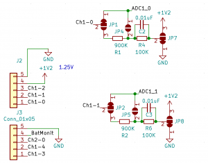
Each ADC has a set of configuration pads that be used to attenuate the input signal and even offset it to +1.25 Volts, making it possible to read ±12V or 0-24V signals. On channel 0, in the picture, JP 7 is used to enable or disable bipolar measurements, while JP1 and JP4 are used to set the division ratio. Measurements of 0-750mV, 1050mV, 1300mV or 250mV are possible with the built-in attenuation while bypassing the resistor divider.


