Arduino Butler
| SKU: | 908-1 |
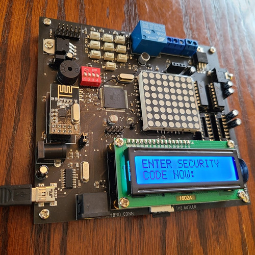
The Butler is an Arduino computer that was designed with a ton of electronic blocks, and a large audio library spread across four audio chips. You can program the butler as you'd like. Below are fundamental video links and code samples that help you to understand how the most up-to-date iterations of the software works.
- The Butler Kickstarter Campaign!
- Unboxing your Butler, and installing the LCD
- Getting Started - Talking to your Butler
In order to communicate with the Butler, you'll need to do the following:
1) You'll need to download the CH340G drivers from github in order for your computer to communicate with the Epoch. Find it here.
If you get a driver failure stating that the "HASH" for the driver is not present, then uninstall the driver, and check out OPTION#2 at this link.
Once you've followed the directions, you can reinstall the driver, and it should work.
2) Download Arduino IDE here: www.arduino.cc/en/software
​3) Watch the above video! The most important details lay within!
4) When you're not using your Epoch, power it off unless you're data logging. This is to protect the board from brown-outs.
5) If you are using the AC-DC wall adaptor to power the Epoch as opposed to USB, make sure you use a surge protector/UPS.
You'll need the following libraries in order to compile and program the Butler with the current code:
PS2Keyboard.h - This library allows for you to use an external computer keyboard and can be found here.
SD.h - I believe that comes defauly with Arduino, but I'm not certain. If not, it can be found on github. It allows for you to read and write to an SD card.
Here is some information on this library.
EEPROM.h - Should come default with Arduino. You shouldn't need to look for it. This library allows for you to write to the EEPROM memory within the chip.
liquidcrystal.h - Should come default with Arduino as well. It allows for you to write to the LCD.
RTClib.h - This library allows for you to read and write to the real time clock (DS3231). It can be found here.
RF24Network.h - Required for the NRF24L01+ wireless tranciever. Here is the library.
RF24.h - Also needed for the NRF24L01+. It can be found here.
The Audio Library
The Butler Audio look-up table can be found here. There are four tabs. There are instructions in this document that tell you how to play an audio bite, and there are tons of examples in the fundamentals videos and code samples.
Connecting to Bluetooth (HC-04 or HC-06)
Getting Started with the HC-06/HC-04 and Roboremo! - To use Bluetooth capabilities with the Butler you will need to download the Roboremo app, and use an existing Roboremo UI and the HC-06 or HC-04 Bluetooth tranciever to work with the bluetoothtest() program. Make sure to check out some projects with the HC-06 at instructables.com! You need to download the free version of the Roboremo App! You also need to save the UI file to your phone. Use the following instructions! =D
1) Download the RoboRemo App
2) Download the file below on your phone, and move this file to your RoboRemo folder.
On my phone, the RoboRemo folder can be found in My Files>Device Storage>RoboRemo
3) Once you've successfully moved the file over to the RoboRemo folder, open the RoboRemo app. You do not need to be connected
to the board via to ready this file.
4) Press the Menu button on the top left of your screen.
5) You should now see several options. Select "Interface"
6) You should now see a new menu. Press "Import", and the file below that you've downloaded and moved to the RoboRemo file folder should show up on the screen. Select it, and you should now see the interface that I have designed. You can now connect to your BT relay board, and use it!
​Here is the Roboremo UI file.
Project Videos
- Fundamentals Video#1 - The Keyboard, LCD, and Serial Monitor
- Fundamentals#2 - Breaking out the audio capabilities!
- Fundamentals#3 - State Machines!
How to use the external IO - Analog pins 7 and 11 are the only two pins available to be used to communicate with external circuits. The below videos hows you how to use them. These analog pins can be used as digital inputs, digital outputs, or as their default setting of ADC input. AN11 can also be used to control the active-high relay. To control the relay, set AN11 as a digital output, and short the RLY-IN header with a jumper. When you set AN11 high, then the relay will turn on. Clear AN11 to 0v to turn the relay off. If you're using AN7 and AN11 as inputs, then you don't need to short the 3.2v headers talkied about in the below video, and no declarations need to be made in void setup(). If you are going to set up AN11 and/or AN7 as digital inputs or digital outputs, here are some examples of how to declare them under void setup():
pinMode(A7,OUTPUT);
// AN7 can now be set to 5v or cleared to 0v using the digitalWrite command. It will act like any other digital GPIO (General purpose input/output pin)
pinMode(A11,INPUT); // A11 can now be sampled to see if the line is high or low. For instance:
if(digitalRead(A11) == HIGH){ // If A11 is rading 5v, then set AN7 to 5v (High)
digitalWrite(A7,HIGH)
​}
- The Arduino Butler - How to use the external IO pins
- How to program and test the on-board DS3231 RTC (real Time Clock)
- Version2.0 Software with the NRF24L01+ Wireless Arduino Shield!
- Choose between USB and the External Power Supply - How to choose!
- Communicating via Bluetooth using the Roboremo App and an HC-04/HC-06 Bluetooth Tranciever (See above for Roboremo UI Installation Guide!)


