SparkFun Inventor's Kit for Genuino 101
| SKU: | 1250 |
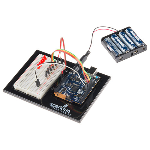
Description: The SparkFun Inventor's Kit for the Genuino 101® board is a great way to get started with programming and hardware interaction with embedded electronics using the Intel® Curie-based Genuino 101 board.
This SIK includes everything you need to complete 21 circuits that will teach you how to control and read the on-board and external sensors, control the Genuino 101 board through your phone, detect and analyze different sounds, and much more. Don't worry; you won't need any previous programming or electronics experience to use this kit. The philosophy behind this kit is that anyone can (and should) play around with cutting-edge electronics. After using this 101 SIK, you'll have the know-how to start creating your own projects and experiments. From building robots and game controllers to IoT and data logging, the world will be your oyster.
The online Experiment Guide for the Genuino 101 board contains step-by-step instructions for how to connect each circuit with the included parts. Full example code is provided and explained, and even includes troubleshooting tips if something goes wrong.
The kit does not require any soldering and is recommended for anyone comfortable reading code libraries and those looking for an alternative to the original SparkFun Inventor's Kit.
Note: The Real-Time Operating System (RTOS) and framework developed by Intel was scheduled to be open sourced in March 2016. It's not possible to interface with it directly; only the Genuino core can do it via static mailboxes.
Circuit Experiments:
- Experiment 1: Blinking an LED
- Experiment 2: Reading a Potentiometer
- Experiment 3: Driving and RGB LED
- Experiment 4: Driving Multiple LEDs
- Experiment 5: Reading a Button Press
- Experiment 6: Reading an SPDT Switch
- Experiment 7: Reading a Photoresistor
- Experiment 8: Color Mixing with the RGB
- Experiment 9: Reading a Temperature Sensor
- Experiment 10: Driving a Servo Motor
- Experiment 11: Using a Transistor
- Experiment 12: Using the Motor Driver
- Experiment 13: Motor Driver with Inputs
- Experiment 14: Using a Piezo Buzzer
- Experiment 15: Using the Sound Detector Board
- Experiment 16: Using a Shift Register
- Experiment 17: Using an LCD
- Experiment 18: Reading the On-Board Accelerometer
- Experiment 19: Tap Detection
- Experiment 20: Using the On-Board Real Time Clock (RTC)
- Experiment 21: Using the On-Board Bluetooth Low Energy (BLC)
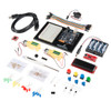
Kit Includes:
- Genuino 101
- Arduino and Breadboard Holder
- White Solderless Breadboard
- Carrying Case
- SparkFun Mini Screwdriver
- 16x2 White on Black LCD (with Headers)
- SparkFun Sound Detector (with Headers)
- SparkFun Motor Driver - Dual TB6612FNG (1A) (with Headers)
- Hobby Gearmotor - 200 RPM (Pair)
- Battery Holder - 4xAA to Barrel Jack Connector
- 74HC595 Shift Register
- Transistor - NPN (BC337)
- 1N4148 Diodes
- DC Motor with Gear
- Small Servo
- TMP36 Temp Sensor
- USB Cable A to B - 6 Foot
- Jumper Wires - Connected 6in. (M/M, 20 pack)
- Photocell
- Tri-color LED
- Red, Blue, Yellow, and Green LEDs
- Red, Blue, Yellow, and Green Tactile Buttons
- 10K Trimpot
- Piezo Speaker
- SPDT Mini Power Switch
- 100 Ohm and 10K Resistors
- 1500 mAh Alkaline Batteries - AA
Documents:


